F40

IP66 Air Borne Mission Computer with Intel® 9th Gen. Processor 6C/12T,18~36V DC-IN, Operation Temp. -40 to +60°C


  • IP66 Air Borne Computer
  • 9th Gen Intel® Xeon® E-2276ML ( 6C,12T) 4.2Ghz
  • Memory support up to DDR4-96GB
  • Nvidia RTX MXM A2000 8GB GDDR6 memory 2560 CUDA cores
  • 1x 2.5” Swappable SATA SSD Tray
  • MIL-461 18V~36V DC , Options for MIL-704/1275 10V~40V DC-Input 
  • MIL-STD 810 509 Salt Fog  Conformal Coating
  • MIL-STD 810 500.6 Low Pressure (50,000 ft) Altitude

Special Request :

  • Frame Grabber : 4xCH HD-SDI
  • Discrete IO : 4x DI/4x DO
  • 10GbE : Dual 10GbE (Intel X710) Ethernet Ports
  • MIL-1553 , ARINC 429

Intel Gold

Technical Profile

Introduction

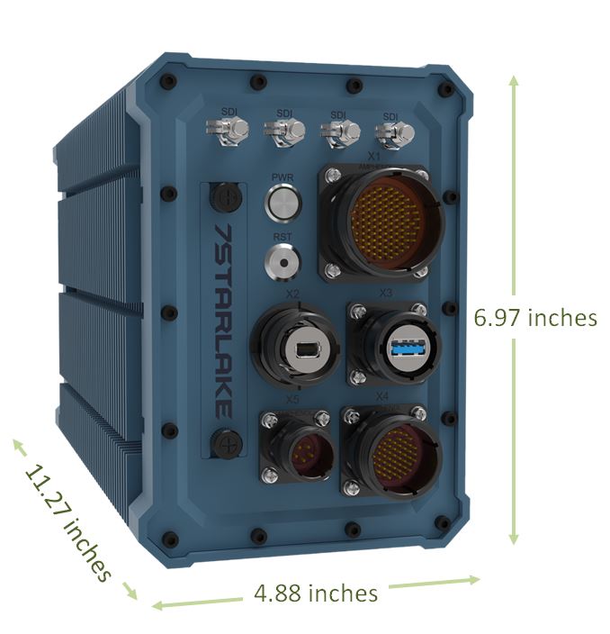
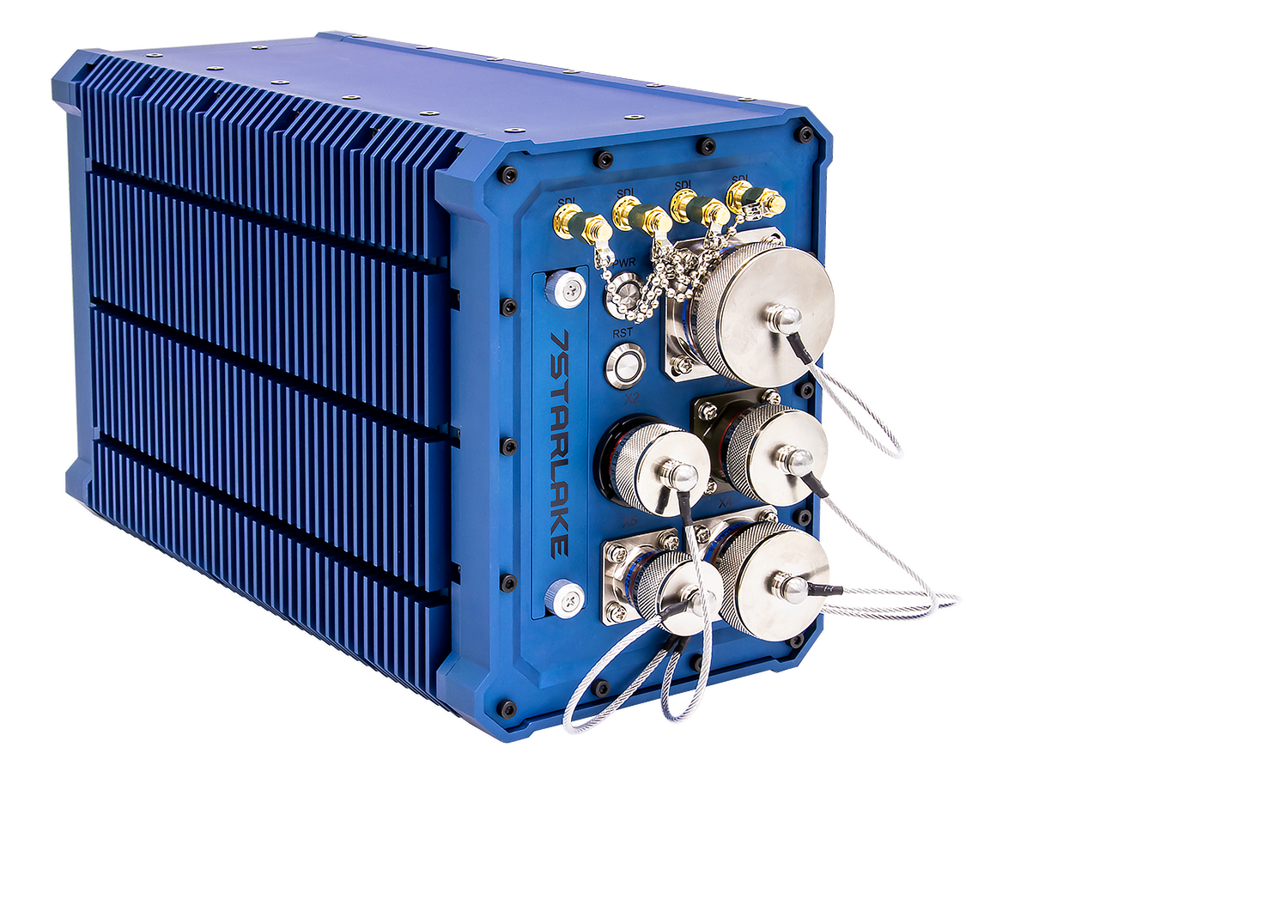
ATR (Air Transport Rack) is a standard that specifies form fit and function of enclosures designed to protect the main internal system. This military enclosure must meet EMI / EMC requirements to prevent noise interference, provide lightning protection and be isolated from small particle contaminants. So, it can be deployed in unmanned aerial vehicles, fighters, and helicopters. To satisfy diverse conditions, ATR chassis are available in different sizes—1/2, 3/4 and Full ATR sizes. Based on 1/2 ATR size, 7Starlake launches a new Rugged Airborne Mission Computer F40.

F40

ARINC 429
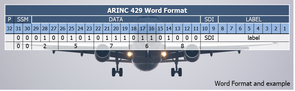
ARINC 429 is the worldwide standard for data transmission in aircraft electronics. It is adopted mostly for commercial aircraft and transport aircraft network protocol standard. Communications, guidance, altitude, altitude reference, flight management, and more are all needed to work together to accomplish a successful flight. The physical connection wires are twisted pairs carrying balanced differential signaling.

The ARINC 429 unit of transmission is a fixed-length 32-bit frame, which the standard refers to as a ‘word’. The bits within an ARINC 429 word are serially identified from Bit Number 1 to Bit Number or simply Bit 1 to Bit 32.

ARINC 429
MIL-STD-1553

MIL STD 1553 is US Military Department of Defence standard that was initially published in 1973.

MIL STD 1553 is a differential serial bus. Also, it is a dual redundant data bus.  Each node is connected to each of the redundant buses.  Secondly, if one should fail, communications can still continue.

There are three types of operating nodes for 1553 Bus:

•A Bus Controller initiates all messages, traffic and commands the remote terminals to transmit/receive data.
•Remote Terminal interfaces the 1553 Bus and Sub System Bridge to other 1553 Buses.  It responds to the bus controller.
•The Bus Monitor listens to messages and records them.
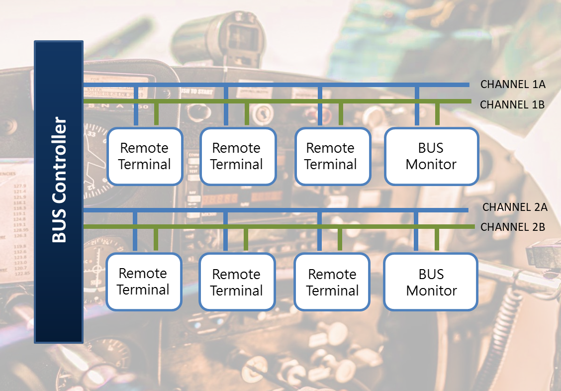
MIL-STD 1533

IT Block Diagram
Features

Computing Features

  • Core i7-9850HE (up to 4.40 GHz),45W
  • Core i7-9850HL (up to 4.10 GHz), 25W
  • Xeon E-2276ME (up to 4.50 GHz), 45W
  • Xeon E-2276ML (up to 4.20 GHz), 25W
  • Memory support up to DDR4-128GB
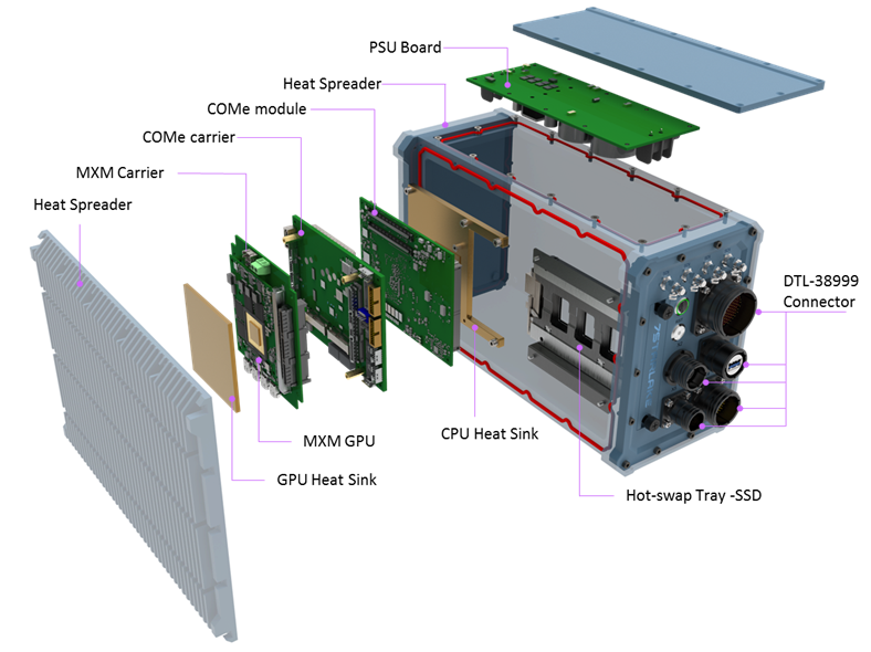
  • IP65 Chassis with D38999 connectors
  • High performance with lower power efficiency
  • 1 x M.2, 2 x Full Size Mini PCIe

F40

I/O and Expansion Options

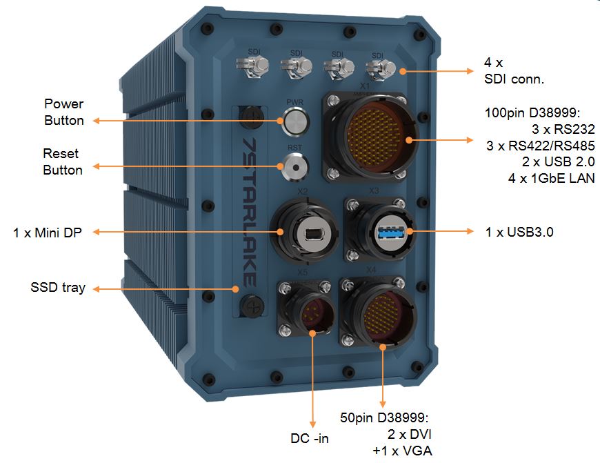
  • X1 : 3 x RS232 + 3 x RS422/RS485 + 2 x USB 2.0 + 4 x 1GbE LAN with 100 PIN D38999 connector
  • X2 : 1 x USB3.0 with USB3.0 D38999 connector
  • X3 : 1 x Mini DP with D38999 connector
  • X4 : 2 x DVI +1 x VGA with 50PIN D38999 connector
  • X5 : 1 x DC in with D38999 connector
  • Others : 1 x 2.5” Easy swap HDD/SSD Tray
    4 x SDI connectors

Environment

  • MIL-STD-704 / 461 /1275 wide range 10-40V DC power module
  • MIL-STD810 Thermal, shock, vibration, Humidity / EMI / EMC conditions
  • Operates up to extended temp -40°C to +60°C

Specifications

System

High Power ProcessorIntel® Core™ i7-9850HE Processor (up to 4.40 GHz), 45W

Intel® Core™ i7-9850HL Processor (up to 4.10 GHz), 25W

Intel® Xeon® E-2276ME Processor (up to 4.50 GHz), 45W

Intel® Xeon® E-2276ML Processor (up to 4.20 GHz), 25W

Memory typeSupport up to DDR4-96GB ,>ECC for Xeon SKU
ChipsetCM246
GraphicIntel® UHD Graphics 630
GPUNVIDIA RTX™ MXM A2000 GA107-980 GPU

4GB/8GB GDDR6 memory, 2560 CUDA cores

BIOSAMI UEFI BIOS
ARINC 429 (optional)6 Channels of ARINC-429

Channels: 4 RX/TX and 2 RX Only Channels. w/ mini-PCIe card

(Alta-dt MPCIE-A429)

MIL -1553(optional)1-2 INDEPENDENT,

DUAL REDUNDANT (A/B) MIL-STD-1553 CHANNELS w/ mini-PCIe card

(Alta-dt MPCIE2-1553)

TPMTPM 2.0 (SLB9665)
Mini PCIe2x Full size (USB / PCIe and 1x micro SIM Card)
Ethernet1x Intel I210-IT / 1 x I219-LM GbE
Power Type10V ~ 40V DC IN
Storage1x 2.5” Easy swap HDD/SSD Tray
GPIO4x GPIO
Operating Temperature-40°C to +60°C degree
Dimension123.95(W) x 177(L) x 286.25(H) mm

FRONT I/O

X13x RS232 + 3x RS422/RS485 + 2x USB 2.0 + 4x 1GbE LAN

with 100 PIN D38999 connector

X21x USB3.0 with USB3.0 D38999 connector
X31x Mini DP with D38999 connector
X42x DVI/DP +1x VGA with 50PIN D38999 connector
X51x DC in with D38999 connector
others1x 2.5” Easy swap HDD/SSD Tray

4x SDI connectors

Environmental

MIL-STD-810 Test


Method 500.5, Procedures I and II (Altitude, Operation):

12,192M, (40,000 ft) for the initial cabin altitude (18.8Kpa or 2.73 Psia)

Method 500.5, Procedures III and IV (Altitude, Non-Operation):

15,240, (50,000 ft) for the initial cabin altitude (14.9Kpa or 2.16 Psia)

Method 501.5, Procedure I (Storage/High Temperature)

Method 501.5, Procedure II (Operation/High Temperature)

Method 502.5, Procedure I (Storage/Low Temperature)

Method 502.5, Procedure II (Operation/Low Temperature)

Method 503.5, Procedure I (Temperature shock)

Method 507.5, Procedure II (Temperature & Humidity)

Method 514.6, Vibration Category 24/Non-Operating (Category 20 & 24,Vibration)

Method 514.6, Vibration Category 20/Operating (Category 20 & 24,Vibration)

Method 516.6, Shock-Procedure V Non-Operating (Mechanical Shock)

Method 516.6, Shock-Procedure I Operating (Mechanical Shock)

ReliabilityNo Moving Parts; Passive Cooling.

Designed & Manufactured using ISO 9001 Certified Quality Program.

EMCMIL-STD-461 :

CE102 basic curve, 10kHz – 30 MHz

RE102-4, (1.5 MHz) -30 MHz – 5 GHz

RS103, 200 MHz – 3.2 GHz, 50 V/m equal for all frequencies

EN 61000-4-2: Air discharge: 8 kV, Contact discharge: 6kV

EN 61000-4-3: 10V/m

EN 61000-4-4: Signal and DC-Net: 1 kV

EN 61000-4-5: Leads vs. ground potential 1kV, Signal und DC-Net: 0.5 kV

CE and FCC

Thermal Solution

Download

AttachmentSize
US20160231790A1 – PCI-104_0_0.pdf (1.14 MB)1.14 MB
Datasheet